A pulse ignition controller should be matched by electrical supply, connector functions, ignition outputs, electrode arrangement, valve interface, sensing method and operating sequence. Two controllers with similar housings can use different wiring and logic, so appearance and wire colour are not sufficient for replacement approval.
Product knowledge base
Verified components used in this guide
1. Record the original controller before sourcing
Photograph the enclosure, label, mounting points, every connector, wire colour, electrode and terminal. Record the appliance model, gas type, control type and the original operating sequence. If the label cannot be read, a short functional video and connector close-ups become especially important.
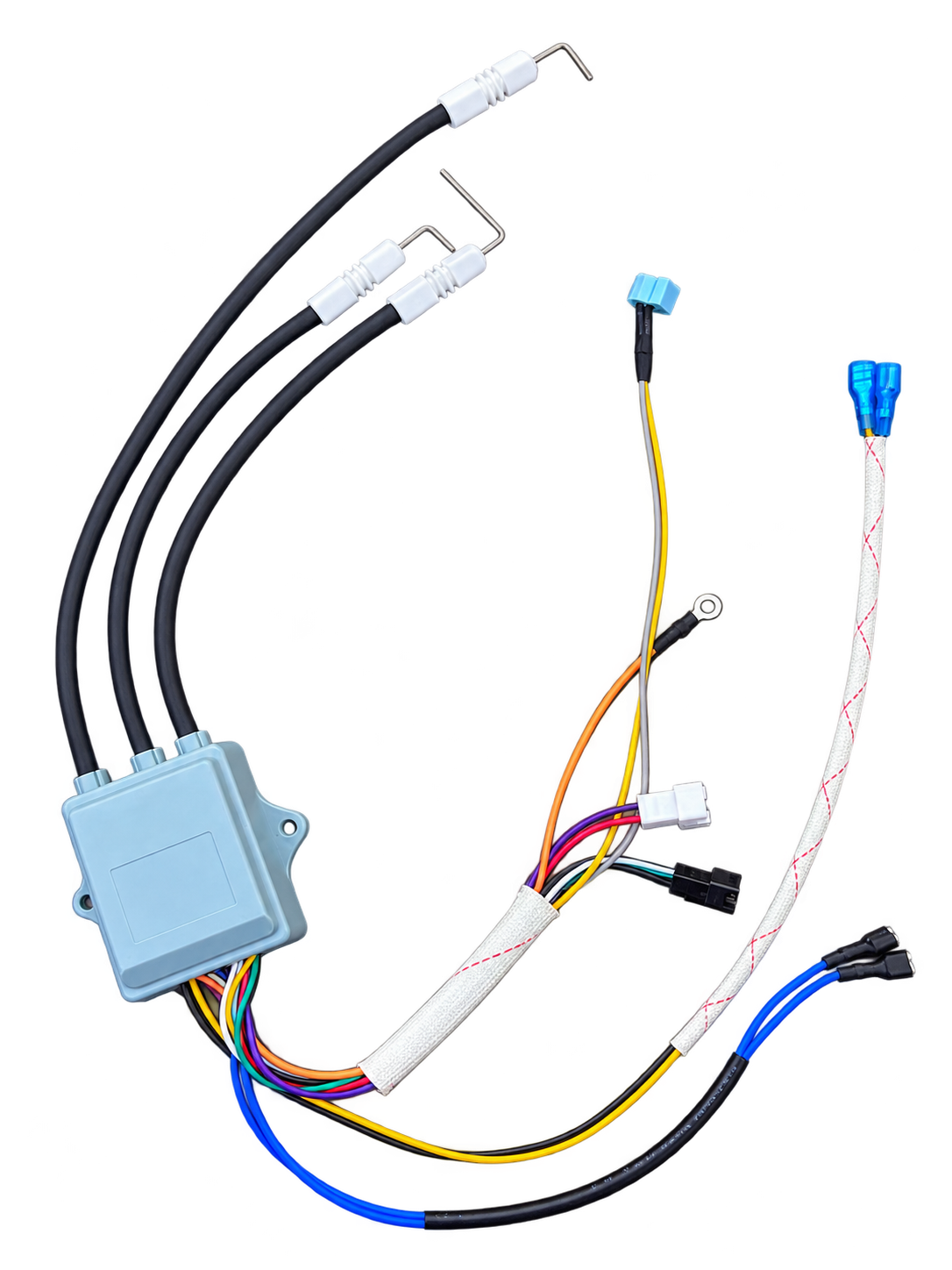
Do not identify the controller only as “three-wire” or “three-output.” Count and describe the high-voltage leads separately from the low-voltage harness and control connections.
2. Confirm the input supply and start-signal circuit
The controller input supply and polarity must match the appliance. The start signal may depend on a water-flow switch or sensor and a user-operated selector switch. Their circuit arrangement should be documented rather than inferred from wire colour.
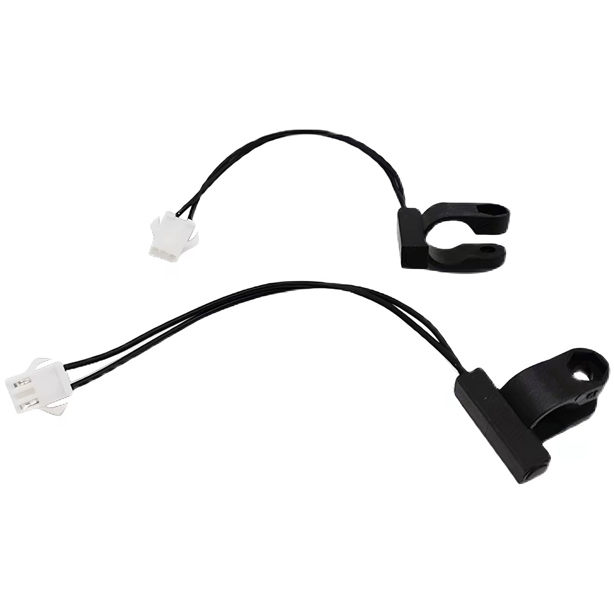
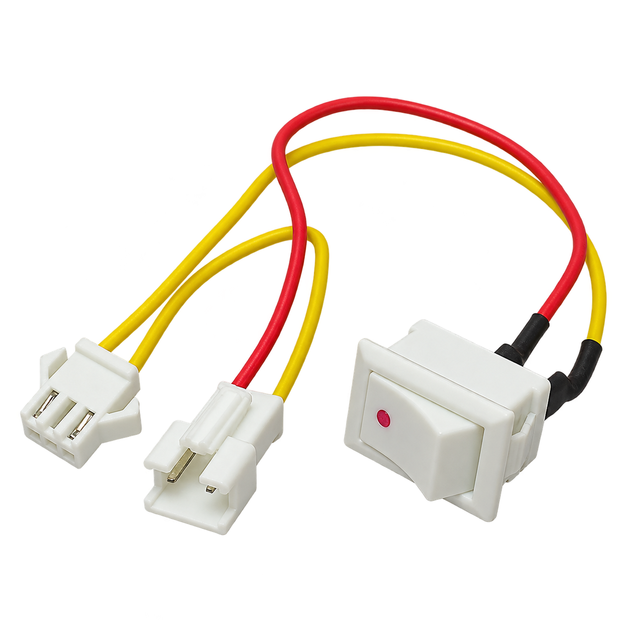
In the photographed knowledge-base example, the water-flow component is a two-wire magnetic reed switch. The reed switch and hot/cold selector switch form part of the start condition for the pulse controller.
3. Identify every high-voltage output and electrode
A controller can use separate leads for ignition electrodes and flame-related functions, depending on the appliance design. Confirm electrode count, lead length, insulation, terminal type, routing and intended connection. The spark gap and electrode position belong to the appliance specification, not to the controller photo alone.
The real Joelwave example shown here uses three black high-voltage leads with white ceramic electrode bodies. This visible arrangement is useful evidence, but it does not replace a pinout or approved sample.
4. Match the gas-control and feedback logic
The pulse controller may coordinate outputs associated with the gas-control assembly and monitor conditions required by the appliance design. Connector shape, coil or actuator requirements, sequence timing and feedback behavior must be confirmed for the exact model.
Avoid publishing or purchasing on an assumed ignition-failure timing, valve voltage or connector function when the manufacturer has not confirmed it. These values should remain project-specific fields in the matching sheet.
5. Validate the matched controller in the appliance
A bench spark check confirms only that high-voltage output is present. The approval test should use the intended appliance and verify the agreed start, ignition, flame response, shut-down and repeated-operation conditions under controlled gas and water inputs.
For a sourcing review, send the original controller or a complete photo set, wiring definition, appliance model, supply information, gas type, electrode arrangement, mounting dimensions and expected order quantity.
Buyer questions
Can two pulse igniters with the same enclosure be interchangeable?
Not necessarily. Input supply, connector pin functions, output count, electrode arrangement, valve interface and timing can differ even when the housings look similar.
Is wire colour enough to identify each function?
No. Wire colours can help document a known sample, but the approved wiring or pinout should define the function.
Does a visible spark prove that the controller is compatible?
No. It confirms only part of the system. Correct sequencing, valve operation, electrode placement, flame response and shutdown behavior still need appliance-level verification.
What information should a buyer send for matching?
Send clear controller and connector photos, the label, appliance model, supply information, gas type, electrode layout, wire and pin functions, mounting dimensions, original operating video and required quantity.